
The Mysterious Torque Converter
July 29, 2014
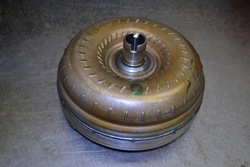 They’re not much to look at, kinda heavy, impossible to get inside of without a lathe to cut them open and above all – get ready for this… fascinating. Behold what I believe is the most incredible component in an automobile drivetrain: the torque converter. More than just a fluid coupling, it’s a physical science masterpiece, yet unfortunately, a mystery to most people – including some of us working on automatic transmissions. Let’s take a look inside.
I’ll admit that for years I took a safe approach when rebuilding a transmission and just replaced the converter with a remanufactured one. I knew it had a few moving parts with some theory behind it, but hey, the things are welded together so you can’t take them apart to inspect inside for problems anyway. Why bother to really understand it? I just put a new one in on each job. This approach worked ok until the 1980’s, when my industry began to deal with a new device auto manufacturers installed in torque converters. It was the lockup clutch. Although it increased fuel mileage for car owners considerably, the torque converter clutch gave technicians something we had never seen before – problems like slipping, chattering and trouble codes. Because the clutch was controlled by not only the computer, but also electronic and hydraulic circuitry in the transmission, we now had to understand how a torque converter worked inside. Fortunately, it’s pretty simple.
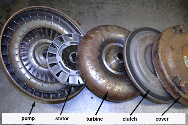
Here’s a typical modern torque converter cut open so we can view the individual parts. This example is actually a 4L60E converter which had been paired to a 4.3 liter engine. Note the part names: pump, stator, turbine, clutch and cover. It is both a torque converter and a clutch.
Very simply, here’s how the converter section works. The cover, the bowl shaped part of the converter which has 3 raised pads for the flywheel bolts, is normally welded to the pump. The pump not only has a hub attached to drive the transmission front pump (a separate type of pump), but also the finned vane looking structure on the other side. As the engine turns the pump and vanes, fluid is centrifugally forced outward (pumped) against the stator. The stator, held stationary by splines on the transmission, has another vane arrangement which redirects fluid flow towards the turbine with a leveraging or torque multiplying effect. The turbine is splined to the transmission input shaft.
The clutch also works simply, but not necessarily like you would normally think.
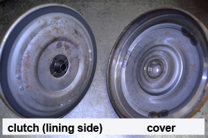
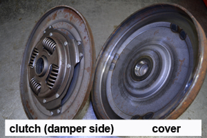
Fluid flow through the center of the input shaft, controlled by a solenoid, floods the area between the cover and the clutch preventing the lining from touching the cover. This is the off state. Converter clutch application occurs when the flow stops. The pressure exerted against the turbine from the pump and stator pushes the clutch against the cover for an on or “lockup” state. In other words, hydraulic flow through the input shaft does not force the clutch against the cover to engage it as you might think. It’s important to understand this concept when diagnosing problems. For example, slipping and chattering of the clutch is caused by the lining wearing out- not from hydraulic leakage.